Red tag Joe's instructions for making LED light strings that run on low voltage for path lighting, light toys, costumes, as seen in various forms for the past 10 summers at the Oregon Country Fair.
LED lighting technology as an enabling
technology.
LEDs are semiconductor devices containing a diode
junction that converts electrical current into monochromatic light. Current required to power LEDs is very low and light created at the diode
junction can be significant. Essentially no infrared is created in the process,
which results in an increase of approximately 80% over incandescent
filament-based illumination.
LEDs are generally packaged in bi-pin or surface mount
configurations and the bi-pin devices are packaged in sizes that can be inserted
as retrofits into many consumer appliances and result in significant increases
in utlity.
This page covers two applications: the creation of very low
cost strings of LEDs (like Christmas tree lights) that can be used as hazard or
trail markings, and the LED retrofit of a MiniMaglight intended to create it as a moderate brightness tasklight well suited to nighttime navigation and compatible with standard rechargable NiCd or NiMh batteries.
Low voltage LED light strings
Materials
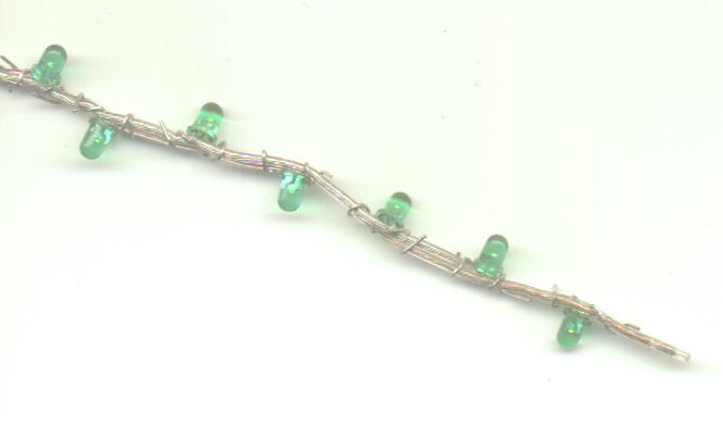
- Speaker hookup wire
- Several 2.6 volt LEDs
- 47 Ohm Current limiting Resistor(s)
- Batteries
- Duct Tape
- Rubberband(s)
Tools
- Pushpin
- Elastomer Winebottle cork
The design of the speaker-wire LED strings was originally developed for use at the Oregon Country Fair in either 1994 or 1995, as Occupational Therapy for pre-fair workers who were sitting around Main Camp and clearly needed something meaningful to do but were looking for something that was not too mentally taxing, was social and could be done in the shade.
Battery holders are essentially "no cost" items, based on duct-tape and readily available Broccoli rubber bands. The speaker hookup wire that is used to mount the LEDs and provide current to them is readily available and reasonably lowcost.
Speaker wire is twin-conductor stranded copper wire packaged in a clear flexible elastomeric sheath and it is available in a polarized variety with one of the strands tinned. Do not purchase untinned variety unless it is the only form available.
Push-pin is forced through the insulation and attempt is made to bullseye the bundle of stranded wire, and the LED lead is pushed through the hole and wrapped around the outside of the wiore, assuring mechanical contact.
Once LED has been inserted and leads twisted, the insulation squeezes stranded wire into contact with LED lead and forms relatively waterproof connection. Copper (untinned) strand is connected to the longer of the two LED leads for consistency (LEDs are diodes and hence polarized. Speaker wire is attached to a live battery pack during assembly, allowing real-time QA during entire process.
- Open circuit condition = LED does not light. This means polarity is wrong or LED lead missed conductor.
- Short circuit condition - rest of the LEDs on the string stop glowing.
The second year's version of the LED strings were dubbed "Anti-Tripping Lights" since they were installed on a wide variety of gates, vehicle exclusion chains, unfinished construction projects and tent guy-wires to prevent night-time injuries.
Since they were expected to be laced into galvanized chains and attached to steel cables, they needed to be insulated. Therefore, the LEDs and their leads were sealed and insulated with a layer or two of clear UPS tape, folded and stuck to itself, which provided a nice reflector diffuser - significantly increasing viewing angle.
Based on my experience with the Rebo Gazebo lights (2 years of operation prefair and during the fair) a pair of alkaline C-cells should power a string of these lights for weeks of continuous operation.
Brightness is controlled by increasing or reducing the resistance of the current limiting resistor. Increasing the brightness is most easily accomplished by adding resistors in parallel - if all the resistors have the same value, simply divide the resitance by the number of resistors. For three 47 ohm resistors in parallel the resistance is 47 over 3 or 16 ohms. Since a single 47 ohm resistor is the right value to drive a 20 MA 2.0 volt LED off a 3 volt source, you could use as many as 1 resistor per LED to drive a string to full brightness, but in practice, 2 or 3 resistors on a string of up to a dozen LEDs should be enough current for most path lighting applications and lower current will substantially increase the burn-time before your batteries need to be recharged. For rechargable batteries with a 1.2 volt cell voltage, the optimum resistor for a single 20 ma LED to full brightness using a pair of NiCd or NiMh batteries is 22 ohms - very very close to a pair of 47 ohm resistors. Final thought: typical values for axial lead resistors are 1/8, 1/4 and 1/2 watt. If each LED is driven to 20 ma, it takes 12 LEDs to draw 240 ma - which is 1/4 watt, but unless you are driving them with a truly inappropriate supply voltage, the current dissipated in the resistor should be a small fraction of the total drain. And IF you are driving from an inappropriate voltage, such as a motor vehicle battery, you should seriously consider using series-parallel wiring or a pulse-width modulated power supply.
Rob Arnold has posted a wonderful online current-limiting resistor calculator. If you put in the junction voltage and current of the LED(s) and the voltage of the battery pack, it will tell you both the vlaue of the resistor and how much current is being wasted in the resistor.
This year (2004), we tried some production light strings for Dancing Dragons Festival of the Forest, and the results of that experience sort of eclipse this set of instructions. They can be found on REWIRING CHEAP CHRISTMAS LIGHT LED STRINGS FOR LOW VOLTAGE USE.
AA or AAA Mini-Maglite
Conversion
NOTE: This section is now approaching a full decade old, and it is blessedly obsolete at this point. There is almost NO POINT in putting a single LED into your mini-maglite, when integrated luxeon-based incandescent lamp replacement technology is available in bi-pin and PR3 bases.
In fact, the ONLY reason to do it is if you have LOTS of mini-maglites and feel that you need one that is not bright. In which case carry on:
Materials
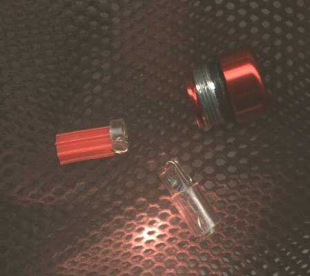
- 2.0 - 2.6 volt T-1-3/4 Super Hi Brightness LED
- 1.8 to 47 Ohm Current limiting Resistor (see below)
- Elastomer tubing
Tools
- 1/8" Drill bit, preferrably a tapered bit
- Needlenose pliers
- Scissors
Anthony Maglica's Mini Maglite is a classic reinvention of
the battery powered flashlight, and remains one of the finest examples of
industrial design ever offered in retail stores.
The core flaw in Maglica's design is that it is TOO DAMNED
BRIGHT for majority of uses - especially night-time walking. The second flaw is that the bi-pin krypton gas filled tungsten filament bulb that is used as the illumination is not well suited to either the cell voltage available in NiCd AA cells nor the discharge curve
provided by Alkaline AA cells, resulting in both cases in the plating of tungsten from
the filament onto the bulb's envelope, reducing both the filament's service life and the instrument's overall light output.
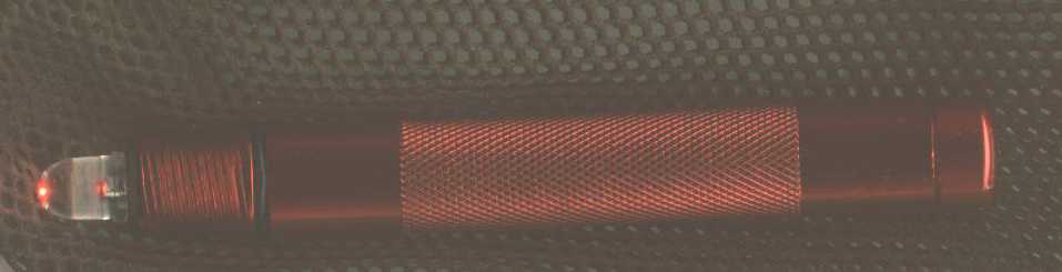
Replacing the bi-pin tungsten bulb with a high-brightness LED
solves both problems, but the dual AA battery arrangement is not well
suited to powering LEDs.
Replacing the spring in the tailcap with a current limiting resistor spring-loaded by an elastomer donut solves the majority of this problem, reducing pointless Infrared radiation that serves only
to reduce the life of the LED and batteries significantly extending battery life.
The choice of resistance value is up to you - if you want an eye-friendly navigation light for walking in the woods at night, and are running rechargable batteries, then something around 20 ohms is probably a good choice. If you want to drive the LED to Photon squeeze-light intensity, then something closer to 2 ohms is what you want.
Joe Breskin
3737 San Juan
Port Townsend, WA
98368
(360)
385 3771
Joe@breskin.com